Executive features
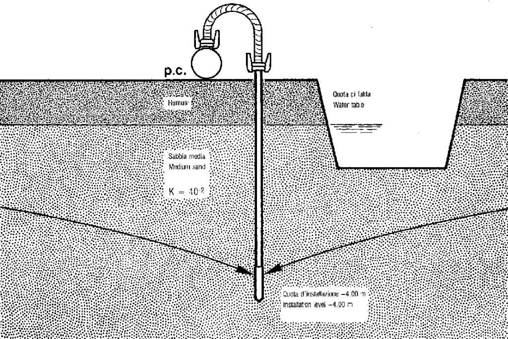
1. Sandy soils
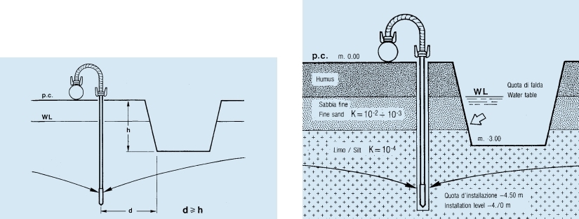
Initially, the wellpoint system found its optimal application in sandy soils. These lands in fact are characterized by porosity and permeability values that are closest to theoretical ones, due to the flow rate of groundwater, and depending on the maximum depression values obtainable in the system. A few pumping hours are enough to obtain a depression of the groundwater surface whose width extends over large surfaces. From the section, you can see how, by exploiting the high range of influence, it is possible to obtain drainage with a single row of wellpoints installed at a considerable distance from the excavation.
2. Sandy soils with impermeable stratifications
The wellpoint system is also effective in these terrains as long as the installation methodology doesn’t change. The wellpoint filters must be protected by special prefilters (sand piles) which have the dual purpose of preventing the filter from clogging and creating a connection (draining diaphragm) between all the layers with different permeability, as shown in the figure. In addition, the system must be installed on all sides of the excavation in order to intercept the flow of water which otherwise, following the most natural and easiest way (sides where the system was not installed), would infiltrate the excavation.
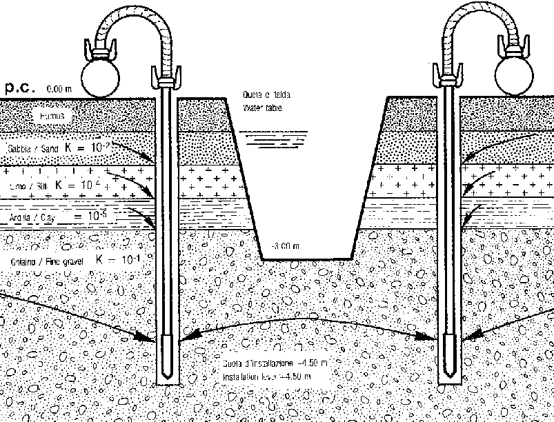
In these soils there isn’t a single cone of influence, as in sandy soils, but as many as the aquifers which must be intercepted by the prefilter. The prefilter consists of a cavity of coarse-grained sand introduced from above, through a pre-drilled hole, after the insertion of the filter tip. The introduction of granita sand, which is deposited on the bottom of the hole by gravity, takes place by maintaining a low-speed water circulation to ensure the washout of the hole. The purpose is double:
– protect the filter from clogging in poorly permeable soils;
– create a drainage communication in stratified soils.
The hole can be made:
– manually, with a suitable probe;
– mechanically, with the aid of drills.
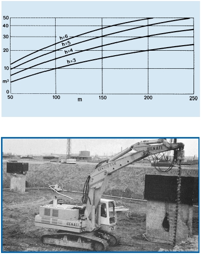
While the manual execution involves a great number of workers, with drilling it acquires considerable speed and, by avoiding mixing the various perforated layers, the hydraulic properties of the soil are kept unaltered. The diagram makes is useful to obtain the quantity of pre-filter sand that must be used on the basis of the planned wellpoint system length. The various curves are obtained according to the depth of execution of the prefilters, which in turn depend on the lowering of the groundwater required.
3. Depth of use
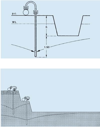
Experience shows that generally the filter tips should be driven at a minimum depth, beyond the bottom of the excavation to be drained, according to the following scheme:
P = h + 1.50 m
The formula described below, valid in general, must not be applied mechanically because it can undergo substantial changes as the stratigraphic conditions of the soils vary. However, there is a limit to the maximum depth of use of the wellpoint system. In fact, the theoretical pressure difference that can be obtained is between the absolute vacuum on one side (pump) and the atmospheric pressure on the other (aquifer).
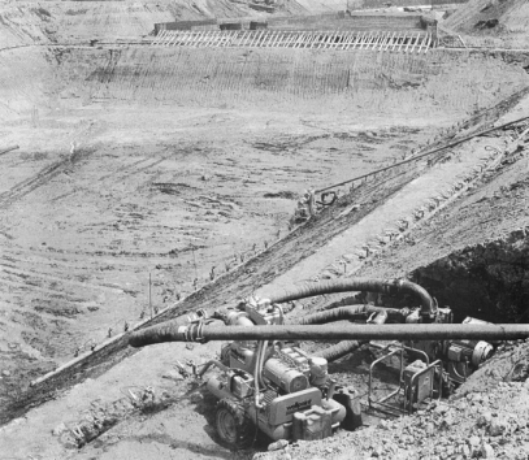
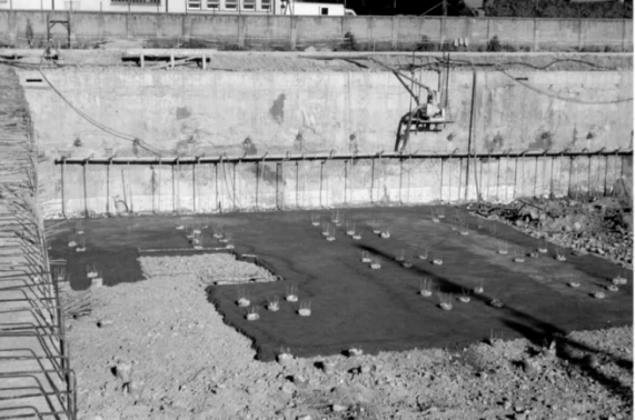
This achievable pressure difference allows water to be sucked from a theoretical maximum height of 10.33 m. In practice, considering the various frictions and head losses, it has been seen that the maximum depth of insertion can be assumed to be – 7 m and, only in a few exceptional cases (possible underpressures), it can reach – 8 m from the installation level. Therefore, when it is necessary to reach high excavation depths with groundwater abatement greater than 5 – 6 m, it is necessary to resort to several concentric rings of wellpoints using the so-called step technique. The interventions in these cases are distributed in phases and each excavation is followed by an installation of systems at a different height, as shown in the sections and photograph.
Of course, carrying out the earthmoving for the application of this technique is not always logistically possible, and in these cases mechanical (sheet piling) or structural (bulkheads and diaphragms) protections are used.
The only system that allows the use of monolithic wellpoints even longer than 8 m is the jet-eductor system (dewatering table). This sophisticated drainage system, applied only in a few specific cases, will be discussed later.
4. Installation distance
Experience shows that it is better to install the wellpoint system at a safe distance, respecting the lower lip of the excavation, equal to the excavation depth according to the diagram. Of course, even in this case, the application cannot be rigid since in construction sites finding the spaces necessary for a correct application of the scheme seen is not always possible for reasons of borders, expropriation, etc. However, it is essential to point out that the closer you get to the embankment with the installation of the system, the more the probability of encountering problems increases during the excavation. In the following pages you will see that there is a fundamental difference in respecting these rules depending on the type of terrain. The positioning of the wellpoint system in soils with impermeable stratifications must necessarily be done at the right distance from the excavation embankments. If the wellpoints are too close to the escarpments, the air present outside the excavation encounters less friction to flow into the prefilter than that encountered by the water of the different layers.
Under these conditions, if air continues to enter the prefilters from the excavation embankments, greater air extraction does not necessarily mean greater effectiveness of the wellpoint system in intercepting the infiltrations of the various layers.
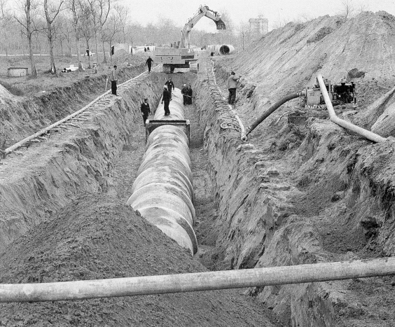
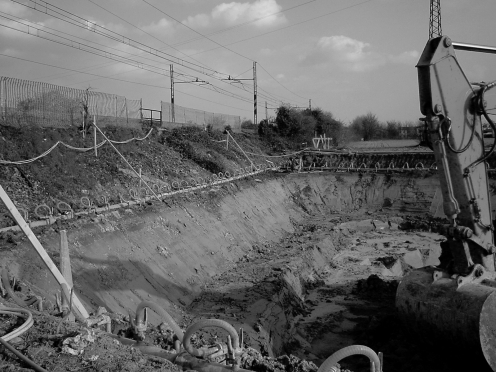
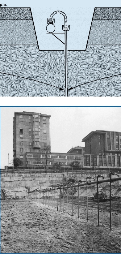
The amount of air entering the prefilters can exceed the air intake capacity of the suction units and this is intuitive when you think of the enormous air flow rates, compared to the hydraulic ones, which can be measured through small holes. In sandy soils with increasing permeability downwards, the action of the wellpoint system, as we have seen, causes a cone-shaped depression on the groundwater that develops below the excavation floor. It is evident that in these conditions the position of the system is not very important, since it can even be placed in the center of the excavation, as can be seen in the diagram and in the photograph on the following page.
The possibility of installing the wellpoint system inside the excavation is exploited especially when buildings with sub-walls of existing structures or with underground floors protected by concrete bulkheads must be built up. In these cases, however, the presence of the system that must remain in operation until the structure is completed determines discontinuity during the casting of the foundations and a whole series of holes that must be closed with particular care after the extraction of the wellpoints.
5. Filter insulation during foundation casting.
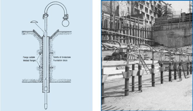
It is therefore extremely important to study the insulation system to ensure that the holes in the foundations – necessary for the operation of the wellpoint system – do not affect the quality of the foundation itself once the filters have been extracted.
The most used methods are:
– protection with PVC plastic pipes;
– protection with corrugated cardboard;
– protection with flanged iron jacket as shown in the diagram.
1. The automatic emergency groups are motor pumps, coupled in parallel to the primary groups (electric or diesel), which intervene automatically and replace them – in the event of a power failure or sudden breakdown – with a sequence of insertions and disconnections automatically controlled by the stop of the primary group or by the vacuum drop in the system.
2. The supplementary emergency groups with piezometric control are reserve motor pumps, connected to the extraction system, which intervene in cases of need to pump out exceptional flow rates controlled solely by the groundwater level through electronic probes inserted in piezometric wells.
3. The timed generator emergency system consists mainly of a connected generator that starts automatically in the event of a power failure.
The automatic intervention impulse of the generator group can be provided:
– from the lack of electricity supply to the primary pumps;
– from the fall of depression in the pumping system.
Through an electronic panel, the various timed pumps start in succession to avoid voltage overloads that are difficult to absorb by the group itself. Naturally, the choice of the emergency system depends on the technical and logistical characteristics of the pumping system and on the basis of safety and cost-effectiveness requirements and therefore the advantages and disadvantages of one or the other solution must be carefully evaluated in design phase and in that of sizing the groundwater lowering system.
